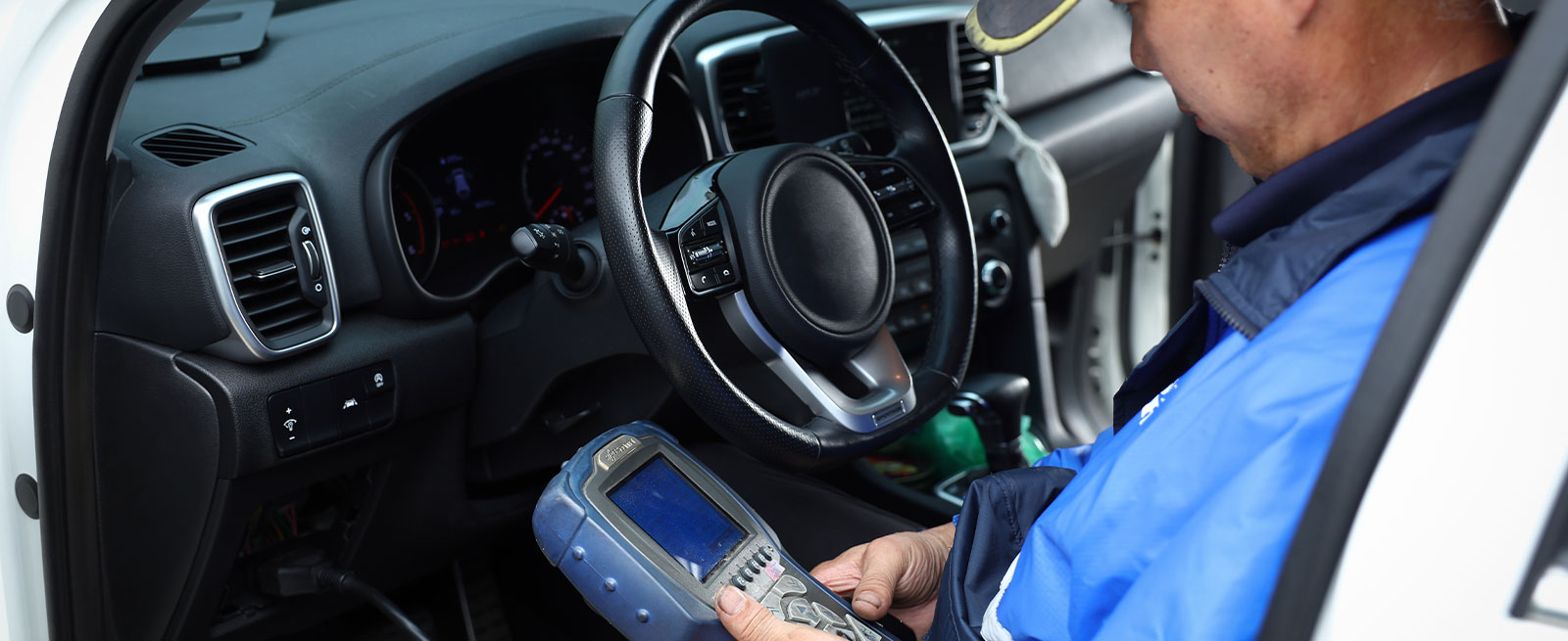

Let’s face it, diagnosing automotive electrical, drivability or emissions-related issues can be a bit challenging. But a DIYer or automotive student armed with good diagnostic skills, a scan tool and reliable diagnostic and repair information can identify and fix most of those issues.
Diagnostic skills will develop naturally with practical experience so in this article, our focus will be on building a good fundamental knowledge of on-board diagnostics (OBD), scan tool operation, diagnostic trouble codes (DTCs) and what to do with DTCs once you’ve found them.
OBD History
In 1968, the Volkswagen Type III became the world's first mainstream production car to successfully use a computerized electronic fuel injection system. It was entirely analog with no self-diagnostic capabilities and was engineered by Bosch. By 1980, on-board computers could be found in many foreign and domestic vehicles.
OBD-I
Although automakers were developing and installing on-board computers with self-diagnostic capabilities in some of their models in the early 1980s, it wasn’t until 1988 that the California Air Resources Board (CARB) required that all new vehicles sold in California from that point on would need to have some OBD capability. These requirements were referred to as OBD or OBD-I, although this official designation wasn’t used until the introduction of OBD-II. Other states began adopting similar requirements soon after.
OBD-I allowed each manufacturer to determine their own type of data link connector (DLC), DTC definitions, communication protocols and hardware interfaces. Non-standardized DTCs from OBD-I vehicles were often read by counting check engine light blinking patterns in the dash or lights on the engine control module (ECU) itself. A technician would jump two pins of a diagnostic connector or push a button on the ECU to start the diagnostic process. DTCs could also be found on some vehicles by using manufacturer-specific scan tools or expensive aftermarket scan tools equipped with various adapter plugs. You can imagine how cumbersome, time-consuming and frustrating diagnostics were back then. Because of the non-standardized testing methods and lack of accurate emissions-specific diagnostic information, OBD-I proved ineffective in supporting an annual testing program. OBD-II changed all that.
OBD-II
By 1996, OBD-II was mandatory for all cars sold in the United States. The system was significantly more standardized using specifications created by the Society of Automotive Engineers (SAE) to comply with California Air Resources Board (CARB) regulations. Diagnosing issues with a wide variety of vehicles became much easier. OBD-II standardized items such as diagnostic protocols, component names, the DLC’s location in the vehicle and what each of its16 pins were for, DTC definitions and a list of vehicle parameters to monitor along with how to encode the data for each. Finally, scan tool designs could also be standardized.
Although only emission-related codes and data were required to be transmitted through the DLC, most manufacturers began using the DLC as the sole communication route through which all systems were diagnosed and programmed.
Connecting a Scan Tool
Tool manufacturers have made today’s OBD-II scan tools quite simple and straightforward to use. But it’s important to remember that a scan tool will only point you in the right direction, it won’t exactly fix the problem for you.
Regardless of which brand of scan tool you own, the following steps should be similar. Following the correct connection steps will allow your scan tool to communicate properly with the vehicle’s computer(s).
- Locate the DLC. If you own a Bluetooth OBD-II scanner, insert it directly into the OBD-II port. If you can’t find the OBD-II port, look in the owner’s manual or an online resource like ALLDATA DIY. It’s usually under the dash and close to the steering column.
- With the ignition switch off, connect your OBD-II scan tool or code reader to the DLC. Turn the ignition key to the ON (or RUN) position. Some scan tools will ask you to start the engine and let it idle.
- Enter the information requested on the scan tool screen and follow the instructions.
- Access the scan tool menu to retrieve any DTCs.
- Identify and understand the DTCs using reliable diagnostic and repair information.
NOTE: In an OBD-II DLC connector, pin 4 (chassis ground) and pin 16 (+ power) are used to power up your scan tool. If your scan tool won’t power up, check for a blown fuse that supplies power to pin #16. If the power is good, check for a broken, loose or corroded chassis ground to pin #4 (Pin #5 is also a ground).
While you’re formulating a diagnostic strategy, it’s important to know that the vehicle’s computers or modules share information with each other…there are no secrets. Primarily emissions-related problems will trigger the MIL. But don’t forget to look for DTCs in all the modules your scan tool communicates with to get a clear picture of how widespread the problem is.
Sometimes you’ll find the same DTC in different modules. For example, if the anti-lock brake (ABS) module recognized a bad wheel speed sensor (WSS) and generated a DTC, that DTC will not only be found in the ABS module but it could also be found in the TCS module, instrument panel cluster (IPC) module and the powertrain control module (PCM). Because they all rely on the wheel speed sensor’s input, the ABS module will alert the other modules.
Understanding DTCs
DTCs can be standard OBD-II or manufacturer-specific. Some scan tools and code readers will only read standard DTCs, some will read both. Active DTCs will light up the MIL. Pending DTCs indicate that a problem has surfaced, but the criteria necessary to change it to an active DTC hasn’t happened yet. Look at all DTCs to get a good snapshot of what’s currently wrong with the vehicle and potentially in the future.
There are thousands of diagnostic trouble codes. A good code reader or scan tool helps us retrieve DTCs, but that’s only half the battle. The other half is knowing what the DTC means and understanding how the system that triggered the DTC operates. For example, if the DTC indicated a fault in the fuel injection system, it would help you develop a solid diagnostic strategy if you understood how that vehicle’s fuel injection system works. To do that, you’ll need access to reliable system description and operation information. The best resource is provided by the vehicle’s manufacturer or an online resource like ALLDATA DIY.
Let’s explore what each character of a standard DTC means. Standard DTCs consist of five characters - a letter followed by four numbers.
- The first character is always a letter that designates which system has the fault.
P (Powertrain): Engine, transmission, ignition, emissions, and fuel system
B (Body): Airbags, A/C, seatbelts and power steerin
C (Chassis): Mechanical systems and functions such as steering, suspension, inside the passenger compartment, axles and the anti-lock brake system
U (Network and vehicle integration): Communication issues between computers and modules plus functions that are managed by the onboard computer system
- The second character is numeric. It is either a 0 or a 1.
0 – Indicates a standard SAE code. It’s also known as a generic or global code, meaning that it applies to all vehicles following the OBD-II international standard. They are government-required codes.
1 – Designates a manufacturer-specific code and is also known as an enhanced code. These codes are unique to a specific vehicle make or model and are not common.
- The third numeric character will give you more precise information about where the issue is. NOTE: The same third character can have different meanings depending on the first two characters. Take powertrain (P) codes for an example. The numbers (0-9) indicate problems with:
0 – Fuel or air monitoring and auxiliary emission controls (includes sensors)
1 – Fuel and air metering
2 – Fuel and air metering – injector circuit
3 – Ignition systems or misfires
4 – Emission control system
5 – Vehicle speed control (cruise control), idle control, and auxiliary inputs
6 – Computer and output circuit
7-9 – Transmission
- The fourth and fifth numeric characters provide exactly what the problem is. They can range from 00 to 99.
DTC Examples
Using what we know about the character’s meaning in a standard DTC, let’s breakdown a few to see what those characters tell us when they are used in a 5-digit DTC. All standard (generic) DTCs must follow this letter/number format.
DTC P0302 – Engine misfire cylinder #2
P - Powertrain code
0 – Standard or generic
3 – Misfire
02 - Cylinder #2
DTC P0420 – Catalyst System Efficiency Below Threshold (Bank 1)
P - Powertrain code
0 – Standard or generic
4 – Emission system
20 – Catalytic converter, bank 1
DTC P1934 - Vehicle Speed Signal
P - Powertrain code
1 – Manufacturer’s specific code
9 – Transmission
34 – Vehicle speed sensor (VSS) signal
What’s Next?
Once you’ve found a DTC and know what it means, what’s the next step? This is where some research is necessary. You could just replace the part based on the DTC, but I caution you against that. Very often the problem is due to a wiring or connector issue or a bad related part. TIP: Most parts suppliers do not take back electrical components so random parts replacements could prove costly. There is plenty of accurate manufacture’s DTC diagnostic information available to help you verify the problem correctly.
After you’ve identified and repaired the problem, use your scan tool to clear the DTC and take the vehicle on a good test drive to verify that the DTC will not return and the problem is truly solved.
Look for our next article where we’ll discuss more scan tool features that will elevate your diagnostic skills.
Not an ALLDATAdiy customer? Learn how a subscription could help you. ALLDATAdiy provides access to repair information on over 44,000 engine-specific vehicles, find yours. Return to see more DIY Helpful Tips.


